
3D quiver plot
This is a comparison to the 3D quiver plot Matplotlib example.
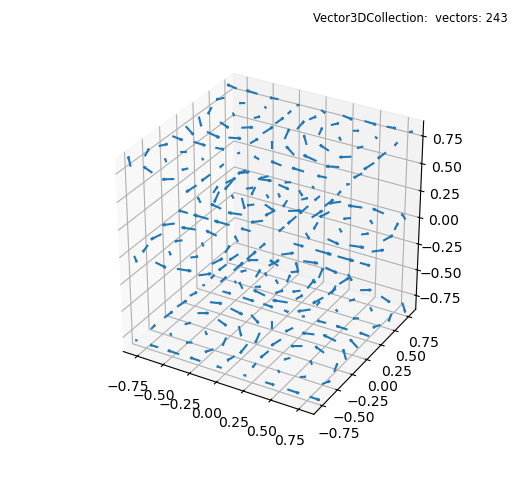
import numpy as np
from matplotlib import pyplot as plt
import s3dlib.surface as s3d

#.. Matplotlib Examples: 3D quiver plot

# 1. Define function to examine ....................................
# +----------------------------------------------------------------------------
# |  The following code between the ========= comments was copied DIRECTLY from
# |  https://matplotlib.org/stable/gallery/mplot3d/quiver3d.html#sphx-glr-gallery-mplot3d-quiver3d-py
# |
# +----------------------------------------------------------------------------
# ===================================================== start of copy.
# Make the grid
x, y, z = np.meshgrid(np.arange(-0.8, 1, 0.2),
                      np.arange(-0.8, 1, 0.2),
                      np.arange(-0.8, 1, 0.8))

# Make the direction data for the arrows
u = np.sin(np.pi * x) * np.cos(np.pi * y) * np.cos(np.pi * z)
v = -np.cos(np.pi * x) * np.sin(np.pi * y) * np.cos(np.pi * z)
w = (np.sqrt(2.0 / 3.0) * np.cos(np.pi * x) * np.cos(np.pi * y) *
     np.sin(np.pi * z))
# ===================================================== end of copy.
# ..... reshape data to N x 3 ......................
location = np.reshape(np.array( [x,y,z] ).T,(-1,3))
vector = np.reshape(np.array( [u,v,w] ).T,(-1,3))
vector *= 0.15

# 2. Setup and map vectors ........................................

vf = s3d.Vector3DCollection(location,vector)

# 3. Construct figure, add surface, and plot ......................

fig = plt.figure(figsize=plt.figaspect(0.92))
fig.text(0.975,0.975,str(vf),
    ha='right', va='top', fontsize='smaller', multialignment='right')
ax = plt.axes(projection='3d', aspect='equal')
minmax = (-0.85,0.85)
ax.set(xlim=minmax, ylim=minmax, zlim=minmax )

ax.add_collection3d(vf)
plt.show()
Colormapping vector fields may enhance the visual interpretation in 3D. Considering a denser distribution of the above data, i.e:
x, y, z = np.meshgrid(np.arange(-0.8, 1, 0.2),
                      np.arange(-0.8, 1, 0.2),
                      np.arange(-0.8, 1, 0.2))
Producing the plot
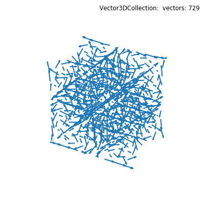
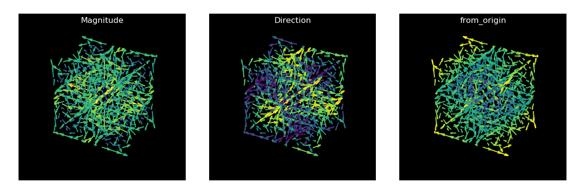
This is similar to the above data set but is visually noisy. Color mapping can reveal patterns when color is based on just the vector magnitude, direction or a color mapping function. See the Magnitude and Direction Visualization example.
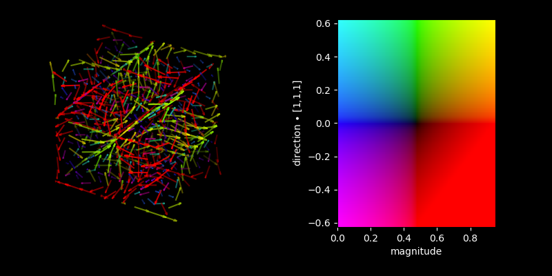
The two magnitude and direction plots can be represented in one plot using a dualcmap colormap, as shown in the following.
The script for the three plot figure is given below:
import numpy as np
from matplotlib import pyplot as plt
import s3dlib.surface as s3d
import s3dlib.cmap_utilities as cmu

# 1. Define function to examine ....................................
# Make the grid
x, y, z = np.meshgrid(np.arange(-0.8, 1, 0.2),
                      np.arange(-0.8, 1, 0.2),
                      np.arange(-0.8, 1, 0.2))
#                      np.arange(-0.8, 1, 0.8))

# Make the direction data for the arrows
u = np.sin(np.pi * x) * np.cos(np.pi * y) * np.cos(np.pi * z)
v = -np.cos(np.pi * x) * np.sin(np.pi * y) * np.cos(np.pi * z)
w = (np.sqrt(2.0 / 3.0) * np.cos(np.pi * x) * np.cos(np.pi * y) *
     np.sin(np.pi * z))

# ..... reshape data to N x 3 ......................
location = np.reshape(np.array( [x,y,z] ).T,(-1,3))
vector = np.reshape(np.array( [u,v,w] ).T,(-1,3))
vector *= 0.4

def from_origin(xyz,uvw) :
    x,y,z = xyz
    return np.sqrt(x*x + y*y + z*z)

# 2. Setup and map vectors ........................................

fields = []

vf = s3d.Vector3DCollection(location,vector,alr=0.4)
vf.map_cmap_from_magnitude()
fields.append(vf)

vf = s3d.Vector3DCollection(location,vector,alr=0.4)
vf.map_cmap_from_direction()
fields.append(vf)

vf = s3d.Vector3DCollection(location,vector,alr=0.4)
vf.map_cmap_from_op(from_origin)
fields.append(vf)

# 3. Construct figure, add surface, and plot ......................

fig = plt.figure(figsize=(12,4),facecolor='w')
axPos = 131
minmax = (-1,1)
for vf in fields :
    ax = fig.add_subplot(axPos, projection='3d', facecolor='k', aspect='equal')
    ax.set_axis_off()
    ax.set(xlim=minmax, ylim=minmax, zlim=minmax )
    ax.set_title(vf.cname, color='w')
    ax.add_collection3d(vf)
    axPos += 1

fig.tight_layout(pad=2)

plt.show()
The dualcmap figure was generated with the following script:
import numpy as np
from matplotlib import pyplot as plt
import s3dlib.surface as s3d
import s3dlib.cmap_utilities as cmu

# custom dualcolormap ....................................
kr = cmu.hsv_cmap_gradient( [0.00,1,0], [0.00,1,1], name='black_red' )
kg = cmu.hsv_cmap_gradient( [0.33,1,0], [0.33,1,1], name='black_green' )
bk = cmu.hsv_cmap_gradient( [0.67,1,1], [0.67,1,0] )
rk = cmu.hsv_cmap_gradient( [0.00,1,1], [0.00,1,0] )
bkr = cmu.stitch_cmap(bk,kr, name='blue_k_red')
rkg = cmu.stitch_cmap(rk,kg, name='red_k_green')
dcmap = cmu.DualCmap(bkr,rkg,'srt',name='mcyr')

# 1. Define function to examine ....................................
x, y, z = np.meshgrid(np.arange(-0.8, 1, 0.2),
                      np.arange(-0.8, 1, 0.2),
                      np.arange(-0.8, 1, 0.2))
# Make the direction data for the arrows
u = np.sin(np.pi * x) * np.cos(np.pi * y) * np.cos(np.pi * z)
v = -np.cos(np.pi * x) * np.sin(np.pi * y) * np.cos(np.pi * z)
w = (np.sqrt(2.0 / 3.0) * np.cos(np.pi * x) * np.cos(np.pi * y) *
     np.sin(np.pi * z))

# ..... reshape data to N x 3 ......................
location = np.reshape(np.array( [x,y,z] ).T,(-1,3))
vector = np.reshape(np.array( [u,v,w] ).T,(-1,3))

def get_magdir(xyz,uvw) :
    direction = [1,1,1]
    incidentDir = np.divide( direction, np.linalg.norm(direction) )
    mag = np.linalg.norm(uvw.T,axis=1)
    dotdir = np.dot(uvw.T,incidentDir)
    return mag,dotdir

# 2. Setup and map vectors ........................................
scale = 0.4
vf = s3d.Vector3DCollection(location,scale*vector,alr=0.2)
vf.map_color_from_op(lambda a,b : dcmap(*get_magdir(a,b)))

# 3. Construct figure, add surface, and plot ......................
mag,dotdir = get_magdir(location.T,vector.T)
mmMagDot = [np.min(mag),np.max(mag),np.min(dotdir),np.max(dotdir)]
minmax=[-.8,.8]
fig = plt.figure(figsize=(8,4),facecolor='k')

ax = fig.add_subplot(121, projection='3d', aspect='equal',facecolor='k')
ax.set(xlim=minmax, ylim=minmax, zlim=minmax,
        xlabel='X', ylabel='Y', zlabel='Z' )
ax.set_axis_off()
ax.add_collection3d(vf.fade())

ax = fig.add_subplot(122, aspect='equal')
y,x = np.mgrid[ 1:0:100j,0:1:100j ]
ax.imshow(dcmap(x,y).T,extent=[ *mmMagDot] )
ax.set(xlabel='magnitude',ylabel= r'direction $\bullet$ [1,1,1]')
ax.xaxis.label.set_color('w')
ax.yaxis.label.set_color('w')
ax.tick_params(axis='x', colors='w')
ax.tick_params(axis='y', colors='w')

fig.tight_layout(pad=2)
plt.show()